Truth tables
Martin McBride, 2017-01-15
Tags and gate 3-input gate truth table
Categories logic logic gates
A truth table is a way of representing the output of a logic gate for every possible set of inputs.
2 input gates
We have already seen the example of a 2 input AND gate, which has a truth table like this:
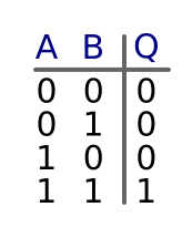
Since there are 2 inputs (A and B), and each input has 2 possible states (0 or 1), there are 4 possible combinations of inputs: (0, 0), (0, 1), (1, 0) and (1, 1). In the case of an AND gate, the output is 0 unless both inputs are 1.
Notice that we arrange the combinations in a particular order. If you look down the columns:
- The values of B are 0, 1, 0, 1
- The values of A are 0, 0, 1, 1
3 input gates
It is possible for a gate to have more than 2 inputs. In the case of a gate with 3 inputs (A, B and C), there are 8 possible combinations (222). Here is the truth table for a 3 input and gate
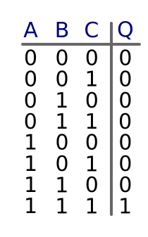
In this case, the output is 0 unless all 3 inputs are 1.
Again, we arrange the combinations in a similar order. If you look down the columns:
- The values of C are 0, 1, 0, 1, 0, 1, 0, 1
- The values of B are 0, 0, 1, 1, 0, 0, 1, 1
- The values of A are 0, 0, 0, 0, 1, 1, 1, 1
Why do we use that particular order? You can think of the inputs as being numbers in binary:
- 000 binary is 0 denary
- 001 binary is 1 denary
- 010 binary is 2 denary
- 011 binary is 3 denary
- etc
So we are just placing the rows in numerical order.
More inputs
It is possible to have logic circuits with 4 or more inputs, and we can simply extend the truth table to account for this.
For example, if there are 4 inputs (A, B, C and D), there will be 16 lines in the table. Extend the sequence of inputs using the same pattern.
Copyright (c) Axlesoft Ltd 2021